555 Timer Circuit Schematic - CMOS 555 Long Duration Red LED Flasher | 555 Timer ... : The circuit layout is for a 555 timer in astable mode.. The 555 can be used to derivatives provide two (556) or four (558) timing circuits in one package.2. The standard 555 timer ic is used in a variety of timer, pulse generation and oscillator applications. Derivatives provide two (556) or four (558) timing circuits in one package. And now a full schematic of the 555 timer oscillator with single step and free run option. Connect power and ground to pins 8 and 1 of the 555 timer (red and black wires).
A better circuit is using a 555 timer. The schematic shows (3) circuits, because one circuit does not work well over the entire vcc range. The 555 and 7555 are called timers or timer chips. To observe the 555 timer in astable mode, let's build a circuit that uses the 555 timer's oscillating output to make. The standard 555 timer ic is used in a variety of timer, pulse generation and oscillator applications.
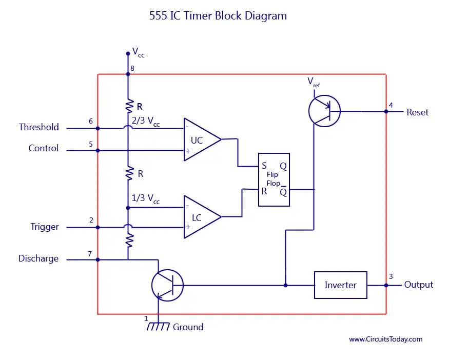
555 Timer IC-Block Diagram-Working-Pin Out Configuration ... from www.circuitstoday.com In this circuit, we will build a clock of about 60hz. The 555 timer, designed by hans camenzind in 1971. The lm555 has a maximum typical supply voltage rating of 16v while the relay's armature coil is enabled at 12v. The above circuit uses a 555 timer u1 in mono stable mode. The 555 timer ic is an integrated circuit (chip) used in a variety of timer, delay, pulse generation, and oscillator applications. An external triggering is required for transition from stable to unstable state. 555 timer ic remains in stable state until the external triggering is applied. Learn about the 555 timer and how it works in astable mode.
The 555 timer can provide time delays ranging from several minutes for one cycle of operation to many thousands of cycles per second.
An external triggering is required for transition from stable to unstable state. The lm555 has a maximum typical supply voltage rating of 16v while the relay's armature coil is enabled at 12v. Introduced in 19723 by signetics,4 the 555 is still in widespread use. Basically, this means that you will have a continuous transition from a high voltage level (determined by and slightly less than your supply voltage) to 0v at a certain frequency (number of times per second). The 555 timer is configured as a monostable multivibrator. Look at the circuit diagram. 7 below, you'll see the circuit schematic of the 555 and the parts relevant to it. • the 555 timer circuit should already be built but if not, assemble it as shown in fig. To observe the 555 timer in astable mode, let's build a circuit that uses the 555 timer's oscillating output to make. The ne555, sa555, and se555 monolithic timing circuits are highly stable controllers capable of producing accurate time delays or oscillation. To make the same circuit as mentioned above without ic 555 timer, we will have to use the following basic electronic components and devices. The schematic shows (3) circuits, because one circuit does not work well over the entire vcc range. With this information you will learn how how the 555 works and will have the experience to build some of the circuits below.
An external triggering is required for transition from stable to unstable state. This cycles 60 times every second. The 555 timer is an integrated circuit, it is extremely versatile and can be used to build lots of different circuits. Before drawing the schematic, we need to create a library where we need to create and store the symbols for components. If once push button is pressed, it drives pin2 of timer the contact of the relay finally drives any external ac load.
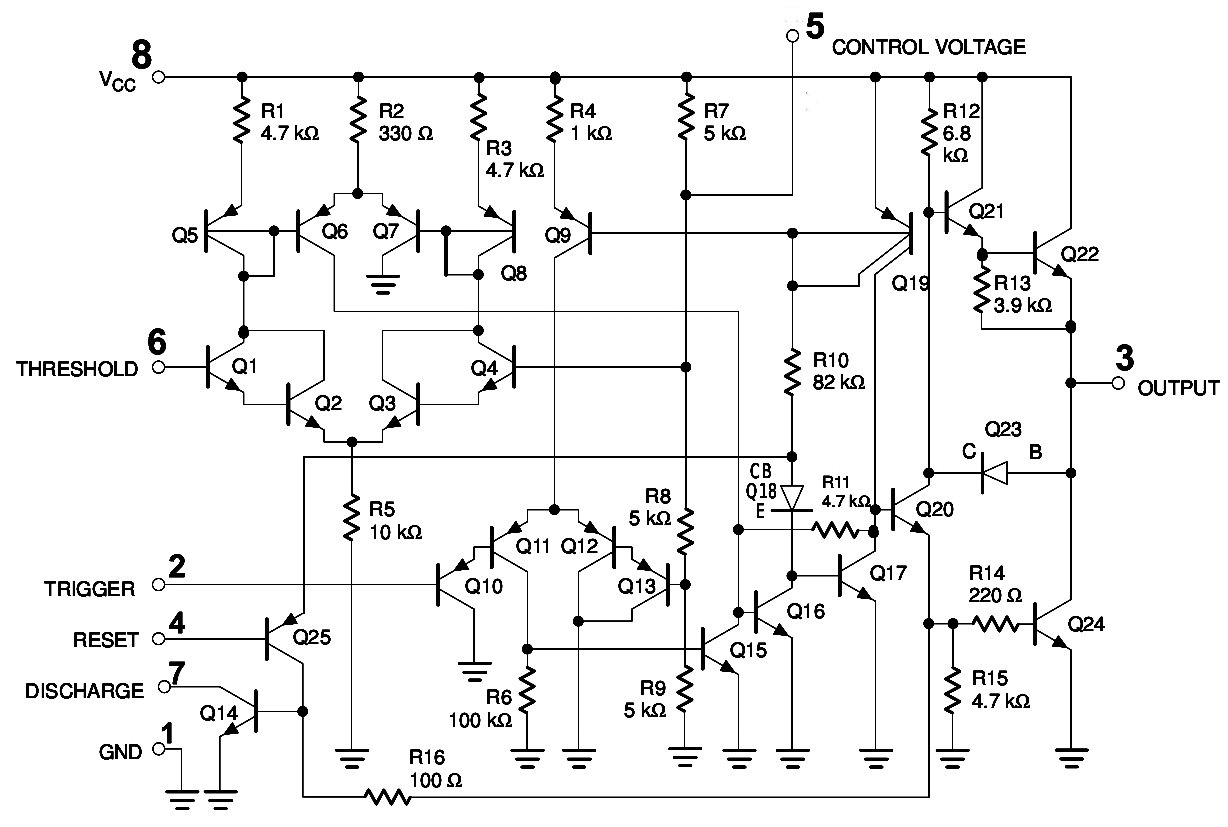
555 Timer IC Pin Diagram Features And Applications | 555 ... from circuitspedia.com We can see that it us made up of 21 transistors, 4 diodes, and 15. The timer generates an output pulse with an on time period determined by the rc network i.e t = 1.1rc. I used a 9v supply. Basically, this means that you will have a continuous transition from a high voltage level (determined by and slightly less than your supply voltage) to 0v at a certain frequency (number of times per second). Before drawing the schematic, we need to create a library where we need to create and store the symbols for components. This 555 timer is in astable mode. The delay time is decided by the r1 & c1.capacitor at pin 5 of timer may have to be increased to about 2uf electrolytic type if. Learn about the 555 timer and how it works in astable mode.
The 555 and 7555 are called timers or timer chips.
I used a 9v supply. Clap switch circuit using ic 555 timer & without timer. Astable mode can produce digital square waveforms that go back and forth between. An external triggering is required for transition from stable to unstable state. The 555 timer ic is an integrated circuit (chip) used in a variety of timer, pulse generation, and oscillator applications. The delay time is decided by the r1 & c1.capacitor at pin 5 of timer may have to be increased to about 2uf electrolytic type if. The 555 timer is configured as a monostable multivibrator. Later it can be used in schematic editor and layout editor. You can explore various applications based on monostable. This tutorial provides sample circuits to set up a 555 timer in monostable, astable, and bistable modes as well as an in depth discussion of wiring info: One configuration of this timer creates a perfect square wave. This is the schematic below for the 555 timer that creates one square wave output. The ne555, sa555, and se555 monolithic timing circuits are highly stable controllers capable of producing accurate time delays or oscillation.
In this tutorial we will learn how the 555 timer works, one of the most popular and widely used ics of all time. The ne555, sa555, and se555 monolithic timing circuits are highly stable controllers capable of producing accurate time delays or oscillation. Si notation all the schematics in this ebook have. The 555 can be used to derivatives provide two (556) or four (558) timing circuits in one package.2. Learn about the 555 timer and how it works in astable mode.
Metronome using astable mode of 555 timer IC from www.engineersgarage.com Si notation all the schematics in this ebook have. You can watch the following video or read the written tutorial below. The 555 timer is a simple integrated circuit that can be used to make many different electronic circuits. The 555 timer, designed by hans camenzind in 1971. It's a simple source of oscillating in the schematic above, notice that the threshold pin and the trigger pin are connected to c1. In this case, the fixed value of the capacitor is. 555 timer ic remains in stable state until the external triggering is applied. These fifteen 555 timer circuits are simple to make with widespread usability.
This tutorial provides sample circuits to set up a 555 timer in monostable, astable, and bistable modes as well as an in depth discussion of wiring info:
I used a 9v supply. The timer generates an output pulse with an on time period determined by the rc network i.e t = 1.1rc. The schematic shows (3) circuits, because one circuit does not work well over the entire vcc range. In this case, the fixed value of the capacitor is 100uf. The 555 and 7555 are called timers or timer chips. This is the schematic below for the 555 timer that creates one square wave output. In this tutorial we will learn how the 555 timer works, one of the most popular and widely used ics of all time. The circuits explained here are 10 best small timer circuits using the versatile chip ic 555, which generates predetermined time intervals in response the image shown below represents the internal schematic of a standard ic 555. Above schematic diagram shows the 555 timer monostable multivibrator circuit. The 555 timer, designed by hans camenzind in 1971. Clap switch circuit using ic 555 timer & without timer. The lm555 has a maximum typical supply voltage rating of 16v while the relay's armature coil is enabled at 12v. The 555 timer is configured as a monostable multivibrator.
Before drawing the schematic, we need to create a library where we need to create and store the symbols for components 555 timer schematic. The lm555 has a maximum typical supply voltage rating of 16v while the relay's armature coil is enabled at 12v.


0 Komentar